Ultrasonic Testing (UT) and Sensors in Industry
Ultrasonic testing and sensors play an important role in the industry in detecting defects in workpieces. But how does ultrasonic testing actually work? In our article, you'll learn not only the basics of UT testing, but also when and why a sound wave is reflected. Read on to discover how this technology helps improve the quality of products.
Ultrasonic testing is an effective method for detecting material defects in electronic components or workpieces. However, ultrasonic sensors are also used for testing in other industrial areas. An acoustic signal is transmitted via the device into the object to be inspected, which then reflects this transmitted ultrasonic wave signal. As a result, faults can be identified, distances measured, fill levels in tanks monitored and relevant information recorded.
How does ultrasonic testing work?
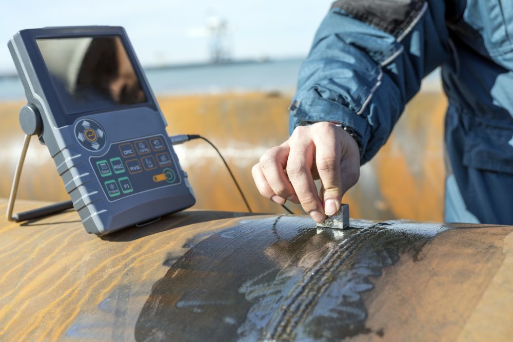
An inspection by means of ultrasound works according to the following principle: In the sensor part of the inspection device there is a piezoelectric disc that can send and receive an ultrasonic pulse. The ultrasonic tester sends the sound wave pulse into the workpiece. The sound passes through it and is reflected off the back wall of the object.
As a result, different information (for example, fill levels, damage or distances) can be recorded and evaluated on the basis of the measured sound waves. A particularly high measurement accuracy is important here.
Measurement accuracy of ultrasonic sensors
The function of ultrasonic sensors can be affected by various environmental influences. These include air temperature, humidity, pressure, air currents or extraneous sound. The temperature has the greatest influence on the measurement.
An ultrasonic sensor works according to the echo transit time method. The time interval between the transmitted pulse and the echo is evaluated. In this way, for example, distances or damage can be determined. For sound propagation in ambient air, for example, the speed of sound is 344 meters per second – at room temperature. It is temperature-dependent at around 0.17 percent per degree Celsius. As a result, the transit time measured by the ultrasonic sensor and the calculated distance are distorted.
To compensate for this effect, sensors with integrated temperature sensors are recommended. Among the ultrasonic sensors from Pepperl+Fuchs, the UB400-12GM model is recommended for this purpose. With its use, measurement deviations can be compensated for by the ambient temperature.
Ultrasound for defect detection in workpieces
Ultrasound can also be used to search for damage, finding cracks, voids or inclusions in a workpiece. When inspecting a flawless object, the pulse passes completely through the device or workpiece. If defects are present, the pulse is partially reflected. Thus, a portion of the signal arrives at the transceiver device earlier than the rest.
The density (Y-axis) and depth (X-axis) of the workpiece can be displayed via a display coupled to the ultrasonic testing device. To perform the procedure, a coupling agent is applied to the component being inspected. This allows damage or weak spots in the workpiece to be identified without having to “destroy” the electronic device or component.
Further applications of ultrasonic waves in industry
- Non-contact level measurement
- Ultrasonic density measurement
- Material processing
- Information processing and transmission
- Materials testing and structural investigation
- Distance measurement and control
- Web edge control
- Height scanning
Fundamentals of ultrasonic testing: What are the testing methods?
There are several methods of ultrasonic testing: These include the pulse-echo method, the through-transmission method and other special inspection methods. These can in turn be subdivided into different measurement and evaluation methods. Bürklin Elektronik presents the three test methods mentioned above:
Through-transmission method
In the through-transmission method, the workpiece is located between the transmitter of the pulse and the receiver part. The signal is transmitted and, if the structure is free of defects, almost completely transmitted to the receiver. If there is an error, the signal is only partially received or not received at all.
This method cannot determine the depth or position of the defect. Therefore, it is only suitable for components with parallel boundaries. It is ideal for thin components (e.g. printed circuit boards) and for defect detection directly below the surface of a workpiece.
Pulse-echo method
In the pulse-echo method, the transmitter and receiver are located in the probe of the ultrasonic measuring instrument. Short (time-limited) sound pulses are transmitted to the workpiece. Initially, these can be seen as transmission pulses on the display.
If the test specimen (= workpiece) is free of defects, the pulses are reflected by the rear wall of the workpiece – this is called the rear wall echo. If there is a defect, the signal is sent back to the test head earlier. The damaged area can be seen on the display.
Special inspection procedures
Several different methods fall under the heading of special inspection methods, such as the phased array method, the TOFDD method, the guided-waves method or the LORUS method. Instead of searching for defect locations, a multi-zone inspection is performed, for example: Designated areas in the workpiece are inspected – in a defined area to be inspected.
Ultrasonic testing: When and why is a sound wave reflected?
An ultrasonic wave is reflected when it is reflected back from a surface. The sound resistance is to be calculated according to the following formula: Sound resistance = density * sound velocity.
The sound propagates in the workpiece at the specific speed of sound until it encounters a change/anomaly in the sound resistance (= sound characteristic impedance). The sound is then reflected at the interface because the sound resistance of air, for example, is lower than that of steel.
Definition of sound characteristic impedance: a physical quantity resulting from the ratio of sound pressure (=p) to sound velocity (v). IF = p/v.
Basic requirement: size and width of the defect area.
In order to measure a defect in a workpiece, it must be larger than half the wavelength lambda of the sound hitting it. The wavelength is calculated by dividing the speed of sound (c) by the frequency of sound (f).
Good to know: The smaller the error to be measured, the larger the ultrasonic frequency (= f) must be selected. The reason for this is that half the wavelength must remain smaller than the error width.
A calculation example for the calculation of the ultrasonic frequency
A calculation example is used to illustrate how an ultrasonic probe must be adjusted in order to be able to output an inspection result. The following assumption: A steel workpiece is inspected at an assumed ultrasonic speed of c = 5,920 meters per second. It is assumed that there is a defect in the material with a defect width of 1.5 millimeters.
The wavelength specified for the example is output as lambda 3.0 millimeters, since this must be smaller than the defect width. The sound frequency required for a measurement is obtained by dividing the speed of sound by the wavelength: f = c / ƛ.
f = 5,920 / 3.0 – the result is a sound frequency of 1.97 megahertz. This means that at least a sound frequency of 1.97 MHz must be selected in order to (just) still be able to detect defects 1.5 millimeters wide in the material steel.
Ultrasonic sensors for industry at Bürklin Elektronik
Industrial ultrasonic sensors have become indispensable in numerous industrial sectors. They perform a wide variety of tasks and functions, such as information acquisition and processing. To do this, they must meet the highest technical requirements.
Apart from the efficient compensation of thermal fluctuations that influence the measuring process, ultrasonic sensors should work reliably and precisely. Depending on the respective application, sensors must have specific properties. For example, in the detection area where sensors are used to inspect large components in production lines.
Product recommendation:
- the UC4000 ultrasonic sensor from Pepperl+Fuchs with an adjustable detection range of 200 to 4,000 millimeters or the
- Pepperl+Fuchs sensor with a rotatable sensor head.
Sensors with a small blind zone – area directly in front of the sensor that is not detected – also increase the efficiency of the inspection process. After all, the faster the object to be detected or inspected is detected, the more smoothly the production system or machine can operate.
Bürklin Elektronik offers a comprehensive range of high-quality ultrasonic sensors for numerous industrial applications. Get to know the product portfolio now.
This might also interest you
-

Energy efficiency
Committed to the Climate: Energy Efficiency Act (EnEfG)
The Energy Efficiency Act (EnEfG) has been in force since November 2023 and obliges authorities, companies and data centers to take energy measures. What does the Energy Efficiency Act actually stipulate? And what strate...
-

Energy efficiency
Light with precision: RGB LEDs with integrated control circuit
Additive color mixing with red, green and blue LEDs, grouped into pixels, opened up new possibilities for displays and lighting designs. When the first modules with integrated circuits (ICs) appeared around ten years ago...
-

Measurement technology
Understanding Power Management ICs: Key Components of Modern Electronics
Efficiently distributing, regulating, and monitoring power is one of the central tasks of electronic systems today. Power density, feature sets, and reliability requirements are constantly increasing. At the same time, p...